LTZ1000 Charger
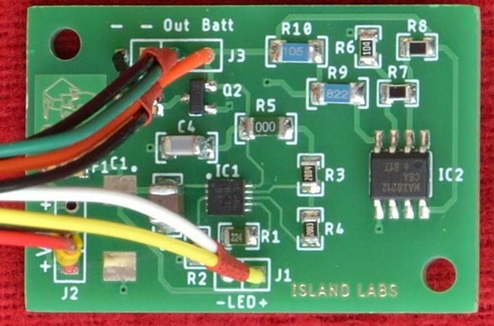
LTZ1000 Charger Board Component Side

Description
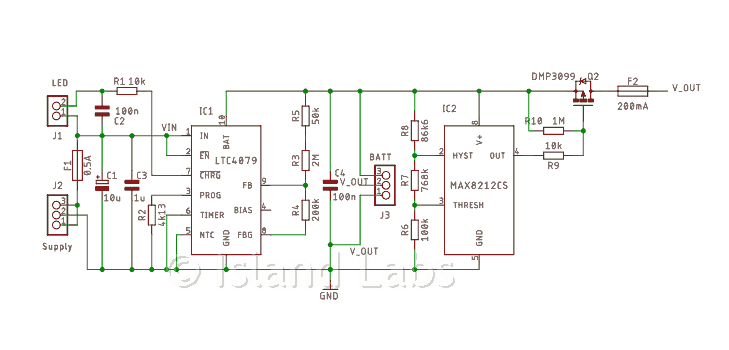
13.2V, 75mA linear charger based on Linear Technology LTC4079. Features constant voltage, constant current, current sensing and reverse current protection. Charging can be terminated by either C/10 or an adjustable timer. A Maxim MAX8212, monitor the battery voltage and disconnect the load when the voltage is too low. Useful for LTZ1000 circuit when an under-voltage condition can destroy the chip.
The charger is designed for NiCd or Pb, 1A/h - 2.2A/h rechargeable battery, and provides 75mA to the load; when the battery is charged, the circuit switches to C/50. If the battery voltage falls below 10V, a voltage monitor disconnects the load, avoiding overheating LTZ1000 due to the increased temperature set-point.
Everyone can order the board from us assembled and tested; use our contact form.
Part List
Part Value Device Package
- C1 10u CPOL-EU SMC_D
- C2 100n C-EU_C1206
- C3 1u C-EU_C1206
- C4 100n C-EU_C1206
- F1 0.5A MF-NSMF050-2 Bourns FUSC3216X85N
- F2 200mA MF-NSMF020-2 Bourns FUSC3216X85N
- IC1 LTC4079 Analog Devices DFN10-3X3
- IC2 MAX8212CS Maxim SO08
- J1 Connector 1X02-PTH M1X2
- J2 Connector 1X03-PTH M1X3
- J3 Connector 1X03-PTH M1X3
- Q2 DMP3099 MOSFET-PCHANNEL Diodes Incorporated SOT23-3
- R1 10k R-EU_R0805
- R2 4k12 R-EU_R0805 0.1% 25ppm
- R3 2M R-EU_R0805 0.1% 25ppm
- R4 200k R-EU_R0805 0.1% 25ppm
- R5 50k R-EU_R1206 1% 100ppm
- R6 100k R-EU_R0805 0.1% 25ppm
- R7 768k R-EU_R0805 0.1% 25ppm
- R8 86k6 R-EU_R0805 0.1% 25ppm
- R9 10k R-EU_R1206 1% 100ppm
- R10 1M R-EU_R1206 1% 100ppm