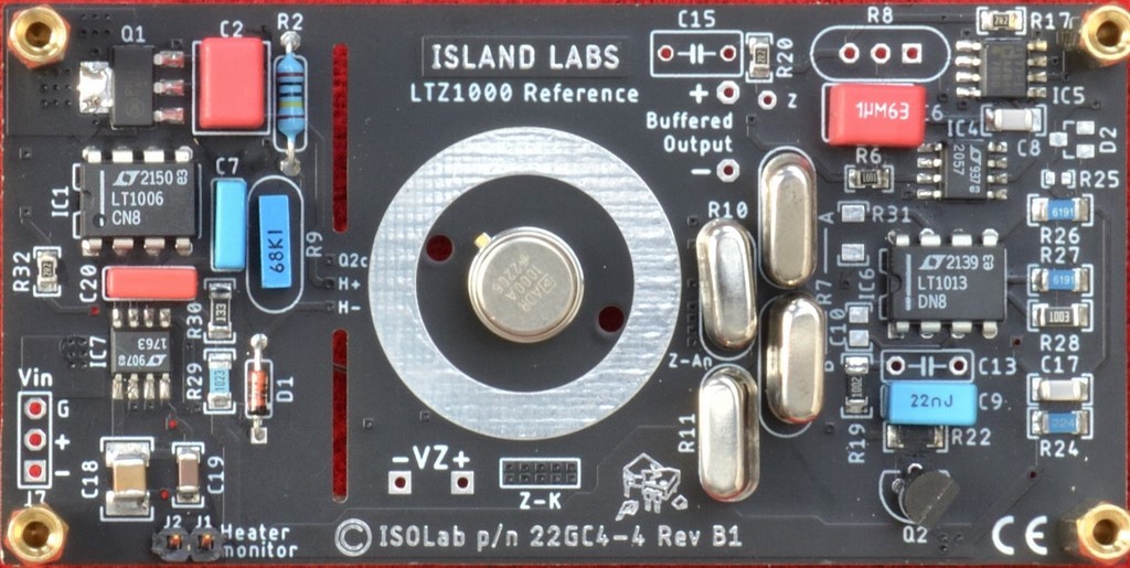
LTZ1000-based Voltage Reference Board
LTZ1000 or ADR1000-based ultra-stable voltage reference board

Very stable (<0.05 ppm/°C), ultra-low-noise and excellent long-term stable reference standard, based on the LTZ1000 from Linear Technology (now Analog Devices).
Features
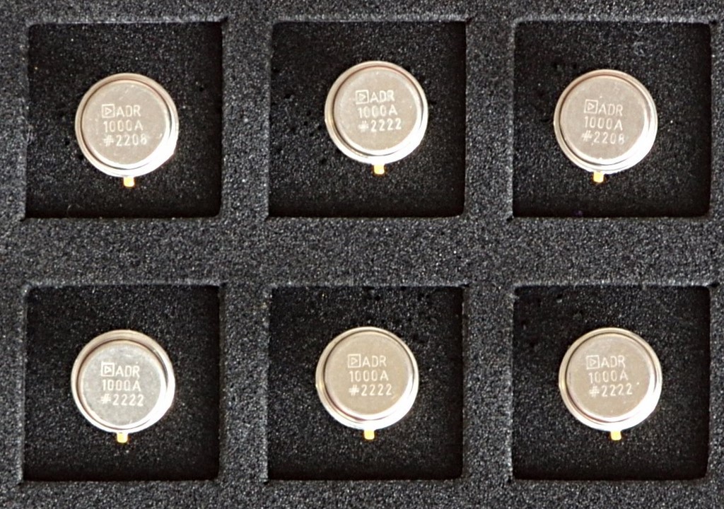
- LTZ1000
- Ageing: <2 ppm/year (temperature set point<60°C and after the first year)
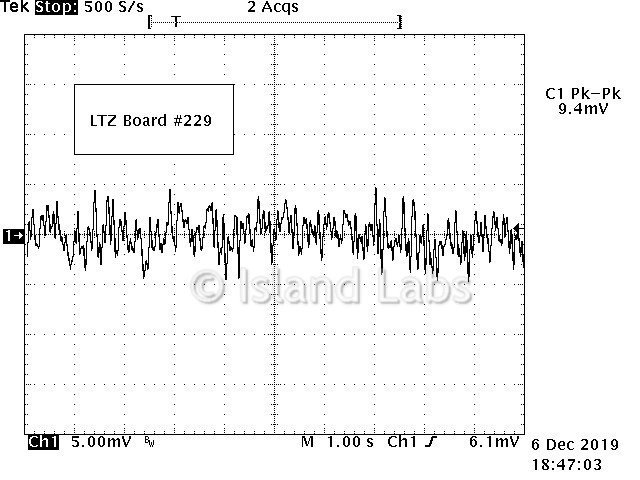
- 1.2µVp-p Typical Noise (0.1Hz - 10Hz Bandwidth)
- ADR1000
- Ageing: <1 ppm/year (temperature set point<60°C and after the first year)
- 0.9µVp-p Typical Noise (0.1Hz - 10Hz Bandwidth)
- Operating temperature: 15°C ÷ 45°C (59°F ÷ 113°F) - the maximum working temperature depends on the set temperature
- Supply voltage: 11V to 16V DC
- Integrated low dropout and low noise voltage regulator
- Work down to 9.5V without sacrificing performance
- Reverse power protection
- Buffered output
- Drive high capacitive load
- Integrated EMI filter
- Low drift, low TC metal foil resistors
- Insensitive to pressure and humidity (only version with hermetic integrated circuits and sealed resistors)
- 4 layers PCB: 91.44 x 45.72 mm (3.60 x 1.80 inches)
- For more information, contact us
Description
The temperature coefficient is measured with the board mounted in a tin-plated steel box (106 x 50 x 26 mm ― 4.17 x 1.97 x 1.02 in) with glass feed-throughs employing Kovar eyelets which allow the copper leads to pass through the enclosure to minimize the thermal EMF. Two cups protect the LTZ1000 from convective air currents; the box is internally coated with a layer of two mm of insulating material.
The TC is measured by the box method, whereby the change in VOUT is divided by the temperature range.
Link to "How is the noise measured?"
Please look at our battery charger specifically designed for use with the LTZ1000.
If you would like more information, please feel free to contact us.
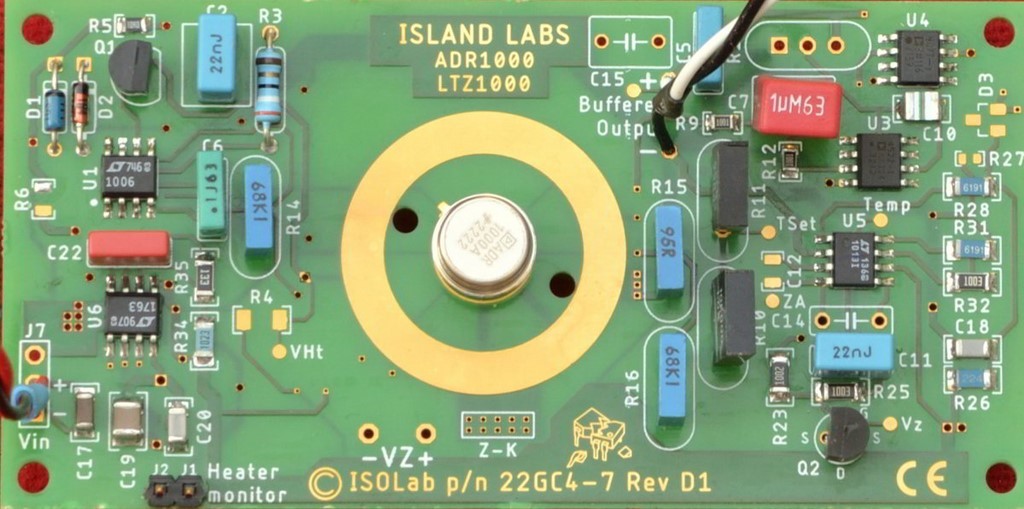
ADR1000 Reference Board
Black Board Reference
ADR1000 SMD Board
ADR1000
JZ1000 Voltage Reference

GZ1000 Reference
Noise in 0.1Hz-10Hz Band
Temperature Coefficient

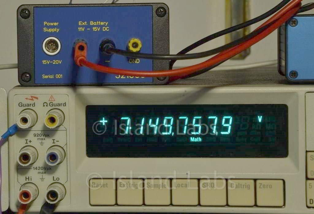
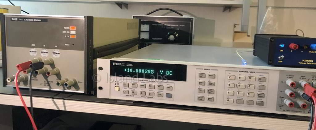
Voltage Standard

Included on the chip, there are a sub surface Zener reference, a heater resistor for temperature stabilisation, and a temperature sensing transistor. External circuitry is used to set operating currents and to temperature stabilise the circuit allows thus maximum flexibility and best long-term stability and noise.
The LTZ1000 and LTZ1000A references can provide superior performance to older devices such as the LM399, provided that the user implements the heater control and adequately manages the thermal layout. To simplify thermal insulation, the LTZ1000A uses a proprietary die attach method to provide significantly higher thermal resistance than the LTZ1000.
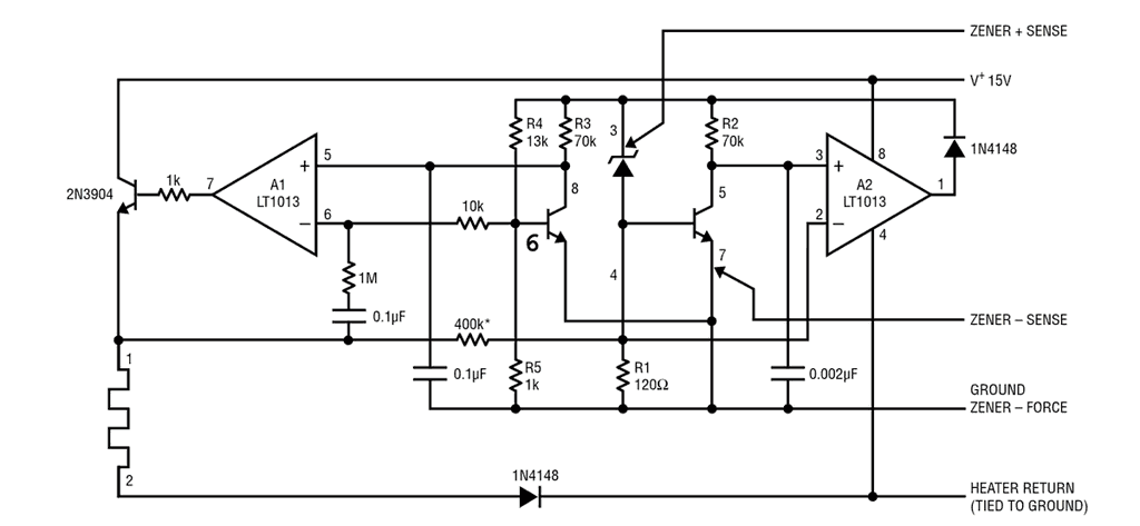
Reference circuit
LTZ1000 and LTZ1000A are capable of providing ultimate voltage reference performance. Temperature drifts of better than 0.03ppm/°C and long-term stability on the order of 1µV per month can be achieved. Noise of about 0.15ppm can also be obtained. This performance is at the expense of circuit complexity since external influences can easily cause output voltage shifts of more than 1ppm.
Thermocouple effects are one of the worst problems and can give apparent drifts of many ppm/°C as well as cause low-frequency noise. The kovar input leads of the TO-5 package form thermocouples when connected to copper PC boards. These thermocouples generate outputs of 35µV/°C. It is mandatory to keep the zener and transistor leads at the same temperature, otherwise, 1ppm to 5ppm shifts in the output voltage can easily be expected from these thermocouples.
Air currents blowing across the leads can also cause small temperature variations, especially since the package is heated. This will look like 1ppm to 5ppm of low-frequency noise occurring over a several-minute period. For best results, the device should be located in an enclosed area and well shielded from air currents.
Certainly, any temperature gradient externally generated, say from a power supply, should not appear across the critical circuitry. The leads to transistor and zener should be connected to equal size PC traces to equalize the heat loss and maintain them at similar temperatures. The bottom portion of the PC board should be shielded against air currents as well.
Resistors, as well as having resistance temperature coefficients, can generate thermocouple effects. Some types of resistors can generate hundreds of microvolts of thermo-couple voltage. These thermocouple effects in the resistor can also interfere with the output voltage. Wire wound resistors usually have the lowest thermocouple voltage, while tin oxide type resistors have very high thermocouple voltage. Film resistors, especially Vishay precision film resistors, can have low thermocouple voltage.
Ordinary breadboarding techniques are not good enough to give stable output voltage with the LTZ1000 family devices. For breadboarding, it is suggested that a small printed circuit board be made up using the reference, the amplifier and wire wound resistors. Care must be taken to ensure that the heater current does not flow through the same ground lead as the negative side of the reference (emitter of Q1). Current changes in the heater could add to, or subtract from, the reference voltage causing errors with temperature. Single point grounding using low resistance wiring is suggested.
Typical Circuit
Setting Control Temperature
The emitter-base voltage of the control transistor sets the stabilisation temperature for the LTZ1000. With the values given in the applications (1k-13k), the temperature is about 60°C - 65°C; this provides 15°C of margin above a maximum ambient of 45°C, for example. Production variations in emitter-base voltage will typically cause about ±10°C difference. Since the emitter-base voltage changes about 2mV/°C and is very predictable, different temperatures are easily set.
Because higher temperatures accelerate ageing and decrease long-term stability, the lowest temperature consistent with the operating environment should be used. The LTZ1000A should be set about ten °C higher than the LTZ1000; this is because typical operating power dissipation in the LTZ1000A causes a temperature rise of about 10°C. Of course, both types of devices should be insulated from the ambient. Several minutes of warm-up is usual.
Specifying Temperature Coefficient (Box Method)
The limits stated for temperature coefficient (TC) are governed by the measurement method.
The TC is most often stated in terms of what has historically been called the "box method".
The overwhelming standard for specifying the temperature drift of a reference is to measure the reference voltage at two temperatures. Divide the total variation (VHIGH – VLOW) by the temperature extremes of measurement (THIGH – TLOW). The result is divided by the nominal reference voltage (usually at 23°C or 25°C) and multiplied by 106 to yield ppm/°C.
This is the "Box" method for specifying temperature coefficient.
Standard Instruments
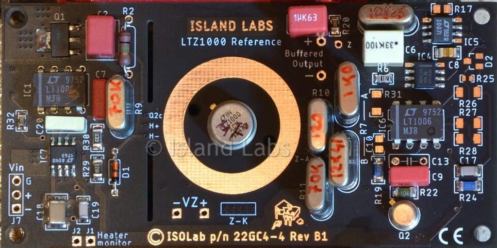
Board with Sealed Resistors
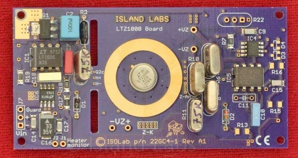
LTZ1000ACH and Ceramic IC

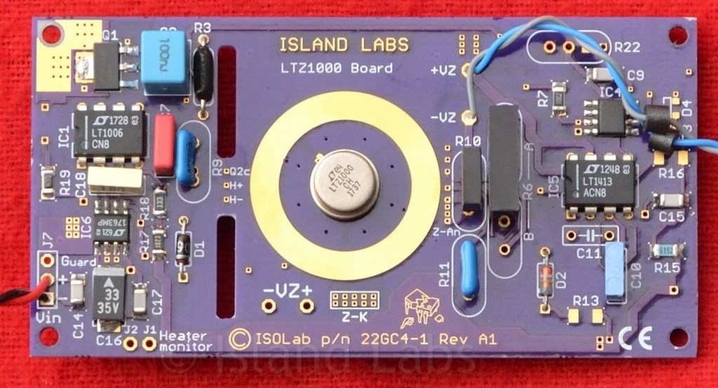
Board with LTZ1000CH
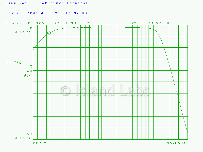
Band Pass Filter