SL201 Amplifier
SL201B & SL201C SINGLE CHIP AMPLIFIER


DESCRIPTION
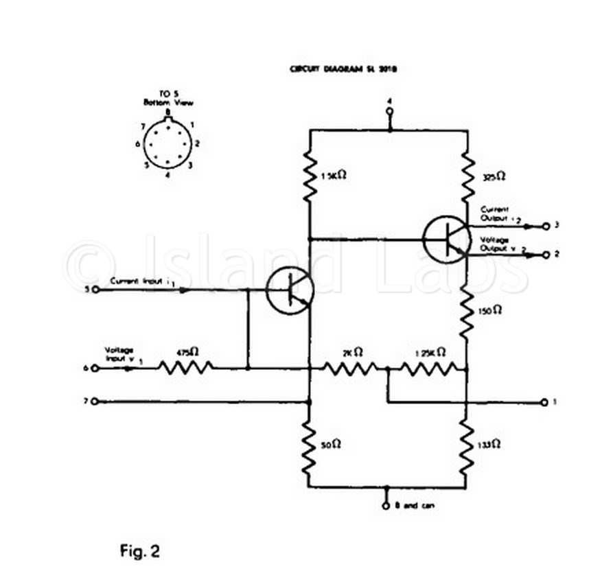
The SL201 amplifier is a silicon, single chip, integrated circuit of the configuration shown in Fig. 2. Provision is made in the amplifier for decoupling the feedback network, and an additional external connection is made to the emitter of the first transistor so that the amplifier may be used in mixer service.Basic characteristics of the amplifier are: typical current gain of 26, typical voltage gain of 14, and typical cut-off frequency of 15 MHz. The maximum peak to peak output voltage is 2.5V.
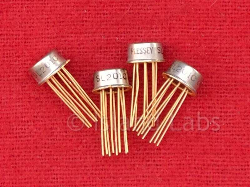
There are various versions; here are showing the B and C versions.
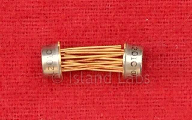
The SL201 is supplied in the 8-lead, metal can, TO-5 package.
ABSOLUTE MAXIMUM RATINGS
- Operating Supply Voltage 15 Volts
- Storage Temperature Range -55°C to +175°C
- Free Air operating Temperature Range -55°C to +140°C
APPLICATIONS
- Operational Amplifier
- Mixer
- High Gain DC Amplifier
SL201B diagram
Operating Instructions
- Since the amplifier is directly coupled throughout, care should be taken to ensure that the source and load impedances do not appreciably affect the bias conditions, e.g. a d.c. source resistance of less than 5 kΩ may cause the last transistor to saturate.
- The external load connected to the voltage output pin should be greater than 300 Ω for good high frequency stability.
- If pin 7 is not connected to pin 8 the input impedance (to pin 5) is typically 300 Ω. This connection also enables the amplifier to be used as a mixer.
- The amplifier may be operated from supply voltages in the range between 6 and 15 volts.