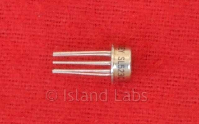
SL523 Dual Log Amplifier
150MHz Wideband Logarithmic Amplifier
FEATURES
- Small Size/Weight
- Lower Power Consumption
- Readily Cascadable
- Accurate Logarithmic Detector Characteristic
- Operating temperature range -55°C to + 125°C
- Storage temperature range -55°C to + 175°C
QUICK REFERENCE DATA
- Small Signal Voltage Gain 24dB
- Detector Output Current 2.1mA
- Noise Figure 4dB
- Frequency Range 10-100MHz
- Supply Voltage +6V
- Supply Current 30mA
DESCRIPTION
The SL523B and C are wideband amplifiers for use in successive detection logarithmic IF strips operating at centre frequencies between 10 and 100M Hz. They are pin-compatible with the SL521 series of logarithmic amplifiers and comprise two amplifiers, internally connected in cascade. Small signal voltage gain is 24dB, and an internal detector with an accurate logarithmic characteristic over a 20dB range produces a maximum output of 2.1 mA. A strip of SL523s can be directly coupled, and decoupling is provided on each amplifier. RF limiting occurs at an input voltage of 25mV RMS, but the device will withstand input voltages up to 1.8V RMS without damage.
The SL523H is supplied in matched sets of eight devices. The gain at 60MHz of the devices in the set is matched to 0.75dB. In all other respects, the device is identical to an SL523B. This selection enables very precise log strips to be produced.
OPERATING NOTES
The amplifier is designed to be directly coupled.
The fourth stage in an untuned cascade will give full output on the broadband noise generated by the first stage.
Noise may be reduced by inserting a single tuned circuit in the chain. As there is a large mismatch between stages, a simple shunt or series circuit cannot be used.
The network chosen must give unity voltage gain at resonance to avoid distorting the log law. The typical value for input impedance is 500 ohms in parallel with 5pF, and the output impedance is typically 30 ohms.
Although a 1 nF supply line decoupling capacitor is included in the can an extra capacitor is required when the amplifiers are cascaded. Minimum values for this capacitor are: 2 stages - 3nF, 3 or more stages - 30nF.
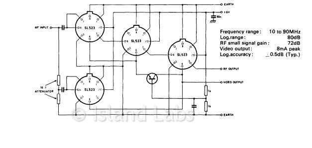
In cascades of 3 or more stages, care must be taken to avoid oscillations caused either by inductance common to the input and output ground of the strip or by feedback along the common video line. The use of a continuous ground plane will avoid ground inductance problems, and a common base amplifier in the video line isolating the first two stages as shown in figure will eliminate feedback on the video line.
TYPICAL PERFORMANCE
Unselected SL523B devices were tested in a wideband logarithmic amplifier, described in RSRE Memo NO.3027 and shown in Fig. 7.
The amplifier consists of six logarithmic stages and two 'lift' stages, giving an overall dynamic range of greater than 80dB. The response and error curves were plotted on a Log Test Set, and bandwidth measurements were made with a Telonic Sweeper and Tektronix oscilloscope.
Fig. 8 shows the dynamic range error curve and frequency response obtained. The stage gains of the SL523 devices used were as shown in Table 1.
The input versus output characteristic (Fig. 8a) is calibrated at 10dB/cm in the X-axis and 1 V/cm in the Y axis. 80dB of dynamic range was attained.
The error characteristic (Fig. 8b) is calibrated at 10dB/cm in the X-axis and 1dB/cm in the Y-axis; this shows the error between the log input v. output characteristic and a mean straight line and shows that a dynamic range of 80dB was obtained with an accuracy of ±0.5dB.
As a comparison, the log amplifier of Fig. 7 was constructed with randomly selected SL521Bs (two SL521Bs replacing each SL523B). Again, a dynamic response of 80dB was obtained (Fig. 9a) with an accuracy of ±0.75dB (Fig. 9b).
Bandwidth curves are shown in Figs. 8c and 9c, where the amplitude scale is 2dB/cm, with frequency markers at 10MHz intervals from 20 to 100MHz. Using SL523Bs (Fig. 8c), the frequency response at 90MHz is 4dB down on maximum, and there is a fall-off in response after 50MHz. Fig. 9c shows that the frequency response of the amplifier falls off more gradually after 40MHz, but again the response at 90MHz is 4dB down on maximum.
These tests show that the SL523 is a very successful dual-stage log amplifier element and, since it is pin-compatible with the SL521, enables retrofit to be carried out in an existing log amplifier. It will be of greatest benefit, however, in the design of new log amplifiers, enabling very compact units to be realised with a much shorter summation line.