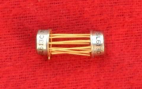
SL613 Limiting Amplifier
Features
- Wide Bandwidth
- Low Noise
- Highly Symmetrical Limiting
- Large Signal Handling Capability
- Supply Voltage: 6V
- Supply Current: 15mA
- Operating Temperature: -30°C to +70°C
The SL613C is a low noise limiting amplifier intended for use as an RF clipper, a limiting stage in IF amplifiers, or an RF compressor in SSB transmitters. It contains a detector, which may be used to detect AM but is particularly intended for use as an AGC detector. The amplifier, which has again of 12 dB when not limiting, has upper and lower 3 dB points of 150 MHz and 5 MHz respectively. It limits when its input exceeds 120 mV rms.
The detected output during limiting is 1 mA.
Circuit Description
The SL613C, like the SL610/11/12, is used with the input and bias pins connected directly and the signal applied through a capacitor. However, and again like the SL610/11/12, the bias may be decoupled and connected to the 'cold' end of a coil or tuned circuit, the input pin being connected to its 'hot' end or a tap.
The supply rail is decoupled internally at RF but, as the gain is dependent on supply voltage, there should be no appreciable LF ripple on the supply. Two separate earth connections are made to minimise the effects of common earth lead inductance; such common earth lead inductance can cause instability. Care should be taken not to introduce it externally.
The RF output is capable of driving a load of 1 kΩ in parallel with 10 pF. If a capacitive load of more than 10pF is envisaged, a resistor should be connected between the output pin and the load. Usually, 50 Ω is sufficient. The output should be isolated at DC by a capacitor.
The detected output consists of a current out of pin 4, which is an NPN transistor collector. This pin must always be more than 3 volts more positive than the earth, even if the detected output is not required (in which case it is best to strap pins 2 and 4).
The SL613C, like the SL610/11/12, is normally used with the input and bias pins connected directly together and the input applied through a capacitor. However, and again like the SL610/11/12, the bias may be decoupled and connected to the 'cold' end of a coil or tuned circuit, the input pin being connected to its 'hot' end or to a tap.
The supply rail is decoupled internally at RF but as the gain is dependent on supply voltage there should no appreciable LF ripple on the supply. Two separate earth connections are made in order to minimise the effects of common earth-lead inductance -such common earth-lead inductance can cause instability and care should be taken not to introduce it externally.
The RF output is capable of driving a load of 1 kΩ in parallel with 10pF. If a capacitive load of more than 10pF is envisaged a resistor should be connected between the output pin and the load. Normally 50Ω is sufficient. The output should be isolated at DC by a capacitor.
The detected output consists of a current out of pin 4, which is an NPN transistor collector. This pin must always be more than 3 volts more positive than earth, even if the detected output is not required (in which case it is best to strap pins 2 and 4).
