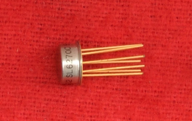
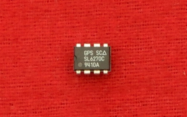
SL6270C VOGAD
Gain Controlled Microphone Preamplifier/VOGAD
Features
- Constant Output Signal
- Fast Attack Time
- Low Power Consumption
- Simple Circuitry
- Supply Voltage: 4.5V to 10V
- Voltage Gain: 52dB
- Ambient temperature: -30°C to +85°C
Description
The SL6270 is a silicon integrated circuit combining the functions of audio amplifier and voice operated gain adjusting device (VOGAD).
It is designed to accept signals from a low sensitivity microphone and to provide an essentially constant output signal for a 50dB range of input. The dynamic range, attack and decay times are controlled by external components.
Voltage Gain
The input to the SL6270 may be single-ended or differential but must be capacitor coupled. In the single-ended mode, the signal can be applied to either input, the remaining input being decoupled to ground. Input signals of less than a few hundred microvolts are normally amplified but as the signal level is increased the AGC begins to take effect, and the output is held almost constant at 90mV RMS over an input range of 50dB. The dynamic range and sensitivity can be reduced by reducing the main amplifier voltage gain. The connection of a 1kΩ resistor between pins 7 and 8 will reduce both by approximately 20 dB. Values less than 680Ω are not advised.
Frequency Response
The low-frequency response of the SL6270 is determined by the input, output and coupling capacitors. Generally, the coupling capacitor between pins 2 and 7 is chosen to give a -3dB point at 300Hz, corresponding to 2.2µF, and the other capacitors are selected to provide a response to 100Hz or less.
The SL6270 has an open loop upper-frequency response of a few MHz, and a capacitor should be connected between pins 7 and 8 to give the required bandwidth.
Attack and Delay Times
Usually, the SL6270 is required to respond quickly by holding the output level almost constant as the input is increased. This 'attack time', the time taken for the output to return to within 10% of the original level following a 20dB increase in input level, will be approximately 20ms with the circuit of Fig.4. It is determined by the value of the capacitor connected between pin 1 and ground and can be calculated approximately from the formula:
Attack time = 0.4ms/µF
The decay time is determined by the discharge rate of the capacitor, and the recommended circuit gives a decay rate of 20dB/second. Other values of resistance between pin 1 and ground can be used to obtain different results.