SL630 Audio Amplifier
Microphone/Headphone Amplifier
Features
- Wide Gain Control Range: over 60dB
- Easy Interfacing
- Mute Facility
- Supply Voltage: 6V to 12V
- Operating Temperature: -30°C to +85°C
- Output Power: 100mW to 200mW
Description
The SL630C is an audio amplifier having 40dB gain and an internal gain control of approximately 60dB, and an output capability of 200mW into a 40 Ω load when used with a 12V supply.
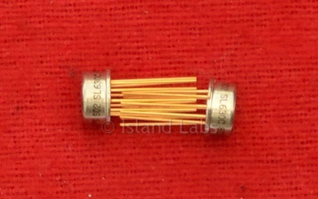
Hermetic metal can and golden pins.
To maintain HF stability — particularly on negative half-cycles — the output (pin 1) should be decoupled by a 1nF, low series inductance, capacitor placed directly between pins 1 and 10 with leads cut as short as possible. This component must be on the integrated circuit side of the output coupling capacitor. At high supply voltages and or low temperatures 10 Ω must be placed in series with this capacitor and 100 pF connected from pin to earth. The output is coupled to the load with a capacitor of low impedance. The load may be resistive or reactive and, for maximum power output, should lie on the supply voltage line. Any higher value of load impedance is quite safe but the device will over-dissipate and eventually destroy itself by overheating if the output is short-circuited. The optimum load, therefore, at any rate with supplies of over 9V, can be regarded as a safe minimum.
The power supply, to pin 2, should be between 6V and 12V and adequately decoupled both at HF and LF. The quiescent power consumption at various supply voltages is shown in the power characteristics, as is the relation of the supply voltage to the optimum load and the maximum power available.
A capacitor connected to pins 3 and 4 defines the high-frequency response of the amplifier. The upper 3dB frequency, f, is given by the formula:
f= 16000/(C+20) (f in kHz, C is in pF).
Pins 5 and 6 are input terminals. They may be used together as a differential input, in which mode they present an impedance of approximately 2 kΩ and result in a voltage gain (without gain control) of 100 (40dB). When the input is obtained from a magnetic transducer or a transformer it is desirable to use the differential input mode since the signal winding may be connected directly to pins 5 and 6 and no other components are required.
An input may also be applied between pin 5 and ground. In this case, the gain is 200 (46dB) and the input impedance 1kΩ. Pin 6 should be earthed by 1500 pF. A coupling capacitor is required between the input and pin 5.
The circuit is muted by grounding pin 7. A muted circuit attenuates an input by about 100dB.
Gain control is applied to pin 8, which has an input impedance of 3.6 kΩ. It must be appreciated that even at full gain the input cannot exceed 50mV RMS without clipping so that at high control levels the output level is limited. The AGC characteristics will vary with temperature but, as shown in Fig. 16 a potentiometer to give manual gain control can be connected to the internal bias point at pin 9 which provides a temperature compensated reference at the voltage at which gain control begins. Pin 10 is the signal earth and negative power supply connection.