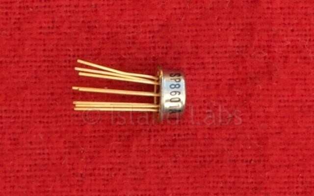
SP8601A 150MHz Counter
Divide by Four 150 MHz Counter
Features
- Current steered output can drive TTL or CMOS
- AC or DC Coupled Input
- Inputs ECL II Compatible
Quick Reference Data
- Supply Voltage: -5.2V
- Power Consumption: 85mW
- Input Frequency: 150MHz
Description
The SP8601 is a fixed ratio emitter coupled logic ÷4 counter with a maximum specified input frequency of 150 MHz but with a typical maximum operating frequency well in excess of this (see Typical Operating Characteristics). The operating temperature range is specified by the final coding letter: 'A' denotes -55°C to +125°C, 'B' denotes 0°C to 170°C.
The SP8601 can be operated with single input drive or with double, complementary, I/P drive. It can be driven with direct coupling from ECL II levels (or from an SP8602 device), or it can be capacitively coupled to the signal source if an external bias is provided.
There are complementary free collector outputs that can have their external load resistor connected to any bias up to 12 volts more positive than VEE.
Operating Notes
- The signal source can be capacitively coupled to the clock input if input bias is provided (See Fig. 6) but is normally directly coupled with ECL II levels. The inputs can be operated either singly or with double complementary input drive.
- The outputs are in the form of complementary free collectors with 1.6mA available from them over full military temperature range (A grade). The outputs can be interfaced to ECL or Schottky. Interfacing to TTL at frequencies above 20 MHz requires low capacitance interconnections and the use of Schottky TTL logic.
- For maximum frequency operation the output load resistor values must be such that the output transistors will not saturate. If the output load resistors are connected to 0V then saturation will occur with resistor values greater than 600 ohms. If only one output is used the other output can be connected to 0V.
- Input impedance is a function of frequency.
- The input can be operated down to DC but input slew rate must be better than 20V/µs.
- All components should be suitable for the frequency in use.
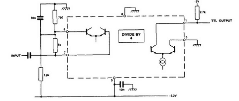
Fig 6