SP8602 500MHz Counter
Divide by Two 500 MHz Counter
Features
- ECL Compatible Outputs
- AC Coupled Inputs (Internal Bias)
- Temperature Range: -55°C to +125°C (A Grade)
Quick Reference Data
- Supply Voltage: -5.2V
- Power Consumption: 60mW
- Input Frequency: 500MHz
Description
The SP8602 is a fixed ratio ECL ÷ by 2 counter with maximum specified input frequencies of 500 MHz. The operating temperature range is defined by the final coding letter: 'A' denotes -55°C to +125°C, 'B' denotes 0°C to +70°C.
The device can be operated with a single input drive or with double, complementary, input drive; in both cases, the input usually is capacitively coupled to the signal source. Two complementary emitter follower outputs are provided.
Operating Notes
The signal source usually is capacitively coupled to the input. A 1nF capacitor is typically sufficient. If the input signal is likely to be interrupted, a 15kΩ resistor should be connected between the input and the negative rail. In the single drive case, it is preferable to connect the resistor to the input not in use; in the double drive case, either input can be used. The addition of the input pull-down resistor causes a slight loss of input sensitivity, but it prevents circuit oscillation under no-signal conditions.
The input waveform may be sinusoidal, but below about 40 MHz the operation of the circuit becomes dependent on the slew rate of the input rather than the amplitude. A square wave input with a slew rate of more than 100 V/µS will permit correct operation down to DC.
The addition of a DC load can increase the output voltage swing to the output emitter follower
Pull-down resistors of 1.5 kΩ to the negative rail provide an increase of typically 25% in the output voltage swing.
Applications
SP8602 interfacing to ECL 10000 and ECL III.
By increasing the output voltage swing using external pull-down resistors (see operating notes), the SP8602 can be coupled directly into an ECL or ECL 10K gate, but there is a reduction of the noise immunity. Where noise immunity is essential, the device can be connected to an ECL 10K or ECL III line receiver.
Divide-by-16 frequency scaler.
The SP8602 interfacing with the SP8601 and high-speed TTL to give a divide-by-16, frequency scaler is shown in Fig. 4.
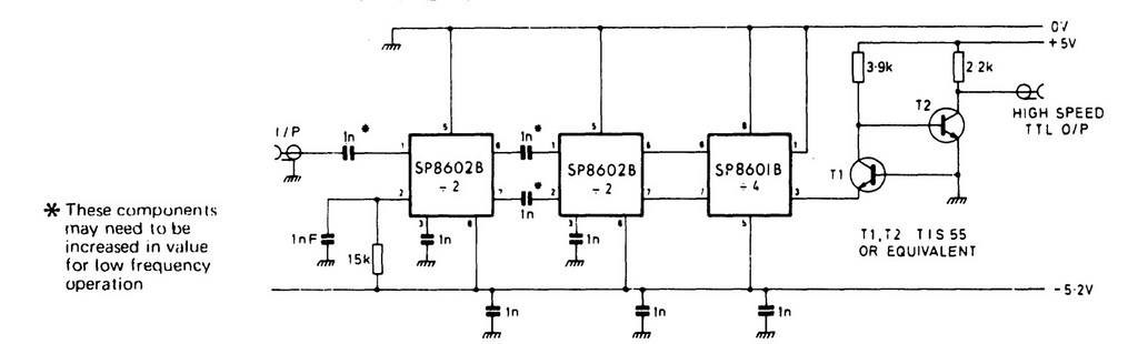
Fig 4