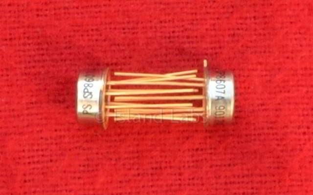
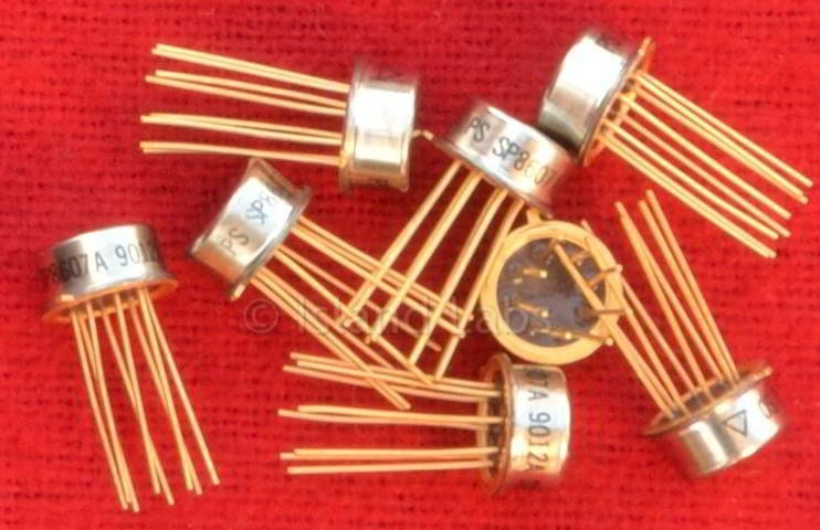
SP8607 600MHz Counter
Divide by Two 600 MHz Counter
Features
- ECL Compatible Outputs
- AC Coupled Inputs (Internal Bias)
- Temperature Range: -55°C to +125°C (A Grade)
Quick Reference Data
- Supply Voltage: -5.2V
- Power Consumption: 70mW
- Input Frequency: 600MHz
Description
The SP8607 is a divide-by-2 counter with a minimum guaranteed toggle frequency of 600 MHz over a 0°C to + 70°C temperature range. The device is designed for capacitive coupling to the signal source to either of the two inputs and it has two complementary emitter follower outputs. Power dissipation is typically only 70 mW with a 5.2V supply.
Operating Notes
All components used with the SP8607 should be suitable for the frequencies involved, resistors and capacitors should be of low inductance types and terminated loads should be kept short to minimise reflections. The test circuit uses positive earth because this minimises noise problems and the danger of accidently shorting the O/P transistors to a negative voltage. However, the device will operate satisfactorily and to the specification, with a negative earth provided that the positive supply is well decoupled to the UHF earth.
There are two complementary inputs connected to an internally-generated temperature-compensated bias point via two 400 ohm resistors. The signal source would normally be capacitively coupled to one of the inputs and the other should be decoupled to earth. If two complementary input signals are available (when cascading SP8607s for example) both inputs should be used.
The input signal can be directly connected to the device either by using a voltage dropping network or by using split lower supplies (see Fig. 4). In this mode the device is very tolerant of the actual values of Vee and VEE although |Vee - VEE| should stay within 5.2V ± 0.25V. A 2.7 kΩ resistor is connected from Vee to the bias pin in the test circuit because this greatly improves the device's ability to operate with large input signals.
It is important that pins 2 and 3 are decoupled by a capacitor in the range 100 - 1000pF because device sensitivity can be reduced by decoupling to a poor earth. In the absence of an input signal, or if the input signal is of very low amplitude, the device may give an output signal of about 250 MHz. This is due to the balanced nature of the internal ÷ 2 circuit and can be stopped if required by connecting a 10 kΩ resistor between the input and the negative rail. (See Fig. 5). This causes a drop in sensitivity of about 100 mV but typical devices still easily meet the 400 -800 mV input amplitude specification. With sine wave inputs below 50MHz the SP8607 miscounts because the slew rate of the input signal is too slow. Below this frequency a square wave input is needed with a slew rate of 100V/µs or more.
The outputs are compatible with ECLII. There is an internal load of 4kΩ on each output. The outputs can be interfaced to ECL10K by addition of a pulldown resistor of 1.5kΩ to the outputs.