SP8610 1GHz Counter
Divide by Four 1000 MHz Counter
Features
- ECL Compatible Outputs
- AC Coupled Input (internal bias)
- Input Frequency: 1500MHz (SP8611B)
- Wide Dynamic Input Range
Quick Reference Data
- Supply Voltage: -5.2V
- Input Voltage Range 400mV to 1.0V
- Output Voltage Swing 600mV Typical
- Temperature Range: -55°C to +125°C (A Grade)
Description
The SP8610/11 UHF counters are fixed ratio ÷4 asynchronous emitter-coupled logic counters with, in the case of the SP8611B, a maximum operating frequency of 1.5GHz over a temperature range of 0°C to +70°C. The input usually is capacitively coupled to the signal source but can be DC-coupled if it is required. The two complementary emitter follower outputs are capable of driving 100Ω lines and interfacing to ECL with the same positive supply. The SP8610/11 require supplies of 0V and -5.2V (±0.25V).
Operating Note
- The SP8610/11 dividers are very simple to use, but standard high-frequency rules should be followed for optimum performance. For example, all connections should be kept short, and the capacitors and resistors should be types suitable for the frequencies involved.
- The input is normally capacitively coupled to the signal source. There is an internal 400 Ω resistor connecting the input to a reference voltage; this biases the input in the centre of the transfer characteristic.
- The reference voltage is brought out onto pin 6, which should be decoupled to the ground plane. This decoupling completes the input signal path to the device and therefore must be very low inductance for optimum performance. The sensitivity of the device can be increased by DC coupling the input signal about ground (see Fig. 1).
- In the absence of an input signal, both DC coupled and capacitively coupled circuits will self-oscillate with an output frequency of approximately 200MHz. This can be prevented by connecting a 10kΩ resistor between the input and the negative rail. This offsets the input sufficiently to stop the oscillation, but it also reduces the input sensitivity by approximately 100mV.
- The SP8610/11 will miscount with low frequency sine-wave inputs or slow ramps. A slew rate of 200V/µs or greater is necessary for safe operation at low frequencies.
- The input impedance of the SP8610/11 is a function of frequency and minimises at about the same frequency as the maximum input sensitivity. So, although it can load the signal source significantly, there is usually enough signal to operate the device satisfactorily when the input impedance is at a minimum. The worst case occurs at the maximum frequency because this is when the input sensitivity is worst.
- The emitter follower outputs require external load resistors. These should not be less than 330 ohms, and a value of 430 ohms is recommended. Interfacing to ECL III/10K is shown in Fig. 2.
- These devices may be used with split supply lines and ground referenced input utilising the circuit of Fig. 1.
Split Supply
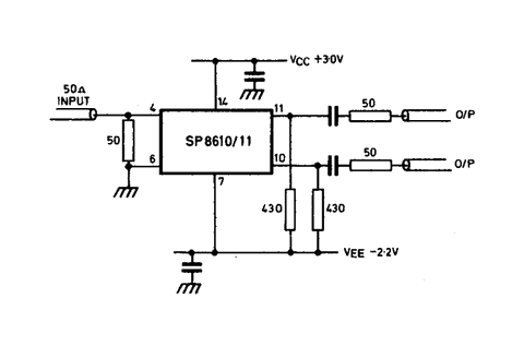
Fig. 1
Interfacing to ECL
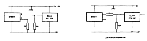
Fig. 2