SP8621A & B 300MHz Counter
300 MHz Divide by Five Counter
Features
- D.C. to 300MHz Operation
- ECL Compatible Outputs
- AC Coupled Inputs (Internal Bias)
- Input Sensitivity: 100 mV p-p
Quick Reference
- Supply Voltage: -5.2V
- Power Consumption: 285mW
- Current Consumption: 55mA
- Temperature Range: -40°C to +85°C (M Grade)
Description
The SP8620, SP8621, and SP8622 are fixed ratio emitter coupled logic, divide by five, counter with specified input frequency range from DC to 400MHz (SP8620), 300MHz (SP8621), and 200MHz (SP8622) respectively.
The operating temperature is specified by the final coding letter:
-55°C to +125°C ('A' grade), 0°C to +70°C ('B' grade), and 40°C to +85°C (‘M’ grade).
The counter is normally capacitively coupled to the signal source and is specified with an input signal range of 400-800mV p-p (-4dBm to +22dBm). There are two bias points on the circuit that should be capacitively decoupled to the ground plane.
Operating Notes
It is recommended that a positive earth plane is used for the circuit layout, thus preventing damage if the output is short-circuited to the earth.
The signal source is normally capacitively coupled to the input. A 1000pF capacitor is suitable at high frequencies, but if lower frequency operation is also required, say below 10MHz, then an additional capacitor should be connected in parallel. The device can be DC coupled if it is needed.
The circuit may self-oscillate when there is no input signal or when the input signal is well below the specified input signal. This can be prevented by connecting a 15kΩ resistor between the input and the negative rail. This causes a loss in sensitivity of up to 100mV p-p.
The input waveform may be sinusoidal but, below about 20MHz the circuit tends to malfunction at minimum amplitude input signals and the condition becomes worse as the frequency is decreased. This is because correct operation of the circuit depends on the slew rate of the input signal. A square wave input with a slew rate greater than 100V/µS ensures operation down to DC.
The output swing of the devices can be significantly increased by the addition of a DC load on the emitter follower output. For instance, the maximum DC load of 1.5kΩ will give an increase of typically 50% in output swing with no effect on input drive level or maximum operating frequency. This allows SP8621 devices to interface directly to ECL II devices with no loss of noise immunity. The values of the decoupling capacitors are not critical, but they should be of a type suitable for the frequencies involved.
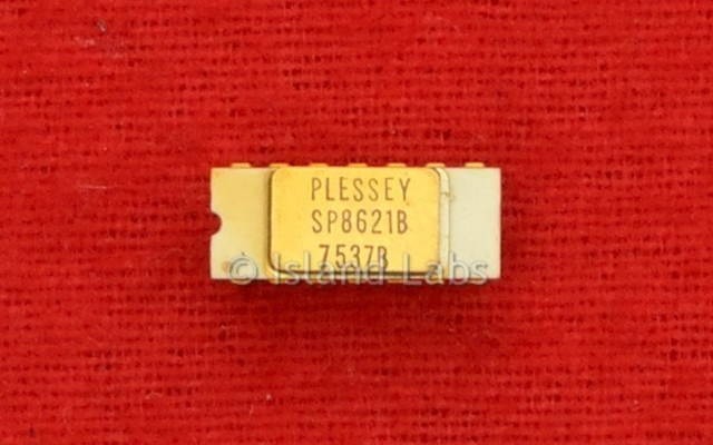
This sample has a white ceramic case and golden pins.