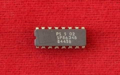
SP8634 Counter
Description
The SP8634B, SP8635B, SP8636B and SP8637B, are divide-by-ten circuit with binary coded decimal outputs for operation from DC up to specified input frequencies of 700 MHz, over a guaranteed temperature range of 0°C to +70°C.
These devices, optimised for counter applications in systems using both ECL and TTL, are intended to be operated between 0V and -5.2V power rails and to interface with TTL operating between 0V and + 5V. The BCD outputs and one of two carry outputs are TTL-compatible, while the second carry output is ECL-compatible. The clock input, which is normally capacitively coupled to the signal source, is gated by an ECL III/ECL 10K-compatible input.
Features
- Direct gating capability at up to 700 MHz
- TTL-compatible BCD outputs
- TTL and ECL-compatible carry outputs
- Wide dynamic input range
Applications
- Counters
- Timers
- Synthesisers
Operating Notes
The devices are intended to be used with TTL and ECL in a counting system —the ECL and the decade counter being connected between voltage rails of 0V and -5.2V and the TTL between voltage rails of 0V and +5.0V.
Provided that this is done, ECL and TTL compatibility is achieved (see Figs. 3 and 4).
The clock is normally capacitively coupled to the signal source: a 1000pF UHF capacitor is normally adequate. If low frequency operation is required the 1000pF capacitor should be connected in parallel with a higher value capacitor. The bias decoupling (pin 1) should be connected to earth via a capacitor —preferably a chip type— but in any case a low inductance type suitable for UHF applications. The devices normally have an input amplitude operating range far greater than the specified 400 to 800 mV peak-to-peak. However, if the decoupling capacitor is not of a UHF type, or it is connected to an earth point that has a significant impedance between the capacitor and the connection, then the input dynamic range will suffer and the maximum signal for correct operation will be reduced.
Under certain conditions, the absence of an input signal may cause the device to self-oscillate. This can be prevented (while still maintaining the specified input sensitivity) by connecting a 68kΩ resistor between the clock input and the negative supply. If the transition of either the clock input or the clock inhibit input is slow, the device may start to self-oscillate during the transition. For this reason, the input slew rates should be greater than 100 V/µs. It should also be noted that a positive-going transition on either the clock input or the clock inhibit input will clock the device, provided that the other input is in the low state.
The BCD outputs give TTL-compatible outputs (fan-out = 1) when a 10kΩ resistor is connected from the output to the +5V rail. In this configuration the outputs will be very slow compared with the clocking rate of the decade and so the state on the BCD outputs can only be determined when the clock has stopped or is inhibited.
The fan-out capability of the TTL carry output can be increased by buffering it with a PNP emitter follower.
