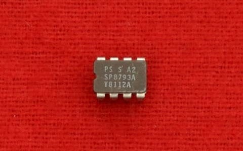
SP8793 Counter
SP8793 225MHz ÷ 40/41 Counter
The SP8793 is a low power, programmable ÷ by 40/41, counter with a temperature range from -40°C to +85°C. It divides by 40 when the control input is in the high state and by 41 when in the low state. An internal voltage regulator allows operation from a wide range of supply voltages.
Operating Notes
- The clock input (pin 5) should be capacitively coupled to the signal source. The input signal path is completed by coupling a capacitor from the internal bias decoupling, Pin 6 to ground.
- The output stage which is an open collector (pin 2 open circuit) can be interfaced to CMOS. The open collector can be returned to a +10V line via a 5kΩ resistor but the output sink current should not exceed 2mA. If interfacing to TTL is required, then pins 2 and 7 should be connected together to give a fan-out of 1. This will increase supply current by approximately 2mA.
- The circuit will operate down to DC, but a slew rate better than 20V/µs is required.
- The mark space ratio of the output is approximately 1.2:1 at 200MHz.
- Input impedance is a function of frequency.
- If no signal is present the device will self-oscillate. If this is undesirable it may be prevented by connecting a 150kΩ between unused input and ground. This reduces the input sensitivity by typically 50-100mV p-p.
- The internal regulator has its input connected to pin 8, while the internal reference voltage appears at pin 7 and should be decoupled. For use with a 5.2V supply, pins 7 and 8 should be connected together and 5.2V applied to these pins. For operation from supply voltages in the range +6.8V to +9.5V, pins 7 and 8 should be separately decoupled, and the supply voltage applied to pin 8.
