Cathodeon PI Network Mark IIQuartz Test Fixture
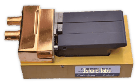
Feature the third key for the insertion of load capacitance.
From the very beginnings of quartz techniques crystals have become not only smaller and smaller, but the frequency limits have always been raised, and the tolerances have constantly been diminished so that production and measuring instruments have become more complicated and expensive. Thus today frequencies must be measured with a precision of better than .1 ppm and equivalent values better than 1%.
In the AT-frequency range, vector voltmeters are available which give a reproducibility of better 1 ppm in arrangements with a frequency generator and the pi-network (or better with network analyser).
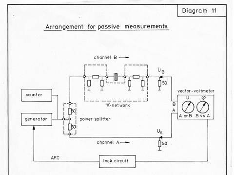
Measurement's setup (Diagram 11)
Properties of Crystal UnitsRearrangement of an older article
Contents
1 Crystal design and equivalent circuit
1a Low and high-frequency crystals
1b Frequency ranges for different cuts
1c Equivalent circuit
1d Pulling
1e Equivalent values of low-frequency crystals
1f Equivalent values of AT-crystals
1g Unwanted responses of AT-crystals
2 Crystal holders
2a State of the art (1970)
2b Frequency ranges for different holders
3 Temperature characteristic of crystals
3a TC of low frequency crystals
3b TC of flexural crystals
3c TC of extensional crystals
3d TC of face shear crystals types DT and SL
3e TC of face shear crystals type CT
3f TC of AT-crystals (thickness shear)
3g TC of biconvex fundamental AT-crystals
3h TC of planoconvex fundamental AT-crystals
3i TC of plain fundamental AT-crystals (with and without bevels)
3k TC of overtone AT-crystals
4 Mechanical properties
5 Ageing
6 Measuring methods
6a General remarks
6b Passive measurement according to IEC 444 and expansion up to 200 MHz
6c Test sets
6d Load capacitance
6e Oscillator circuits - microprocessor
6f Measurement of the dynamic values of the equivalent circuit
6g Measurement of the static capacitance
7 Elaboration of specifications
1 Crystal Design and Equivalent Circuit
1a Low and High Frequency Crystals
1b Frequency ranges for different cut
All crystals have an upper-frequency limit because the thickness should not be lower than 0.055 mm. This value gives 30 MHz for the fundamental crystal, 90 MHz for the third overtone, etc. The lower frequency limit is given by the vibrator diameter for each holder type. As the thickness increases with the lower frequencies, the relation between diameter and thickness becomes smaller and unfavourable.
A survey of the frequency ranges for different cuts used for normal production is given in § 2 b "frequency ranges for different holders".
For AT-crystals the mechanical outlines have a significant influence on the dynamic values of the equivalent circuit and upon the temperature run of frequency and resistance. With the need for lower frequencies and a given holder the vibrators first get bevels and then are manufactured plano-convex and bi-convex. For the same frequency, the more modelled vibrator gives the better performance in quality factor and temperature characteristic. A survey of contours of AT-crystals in different holders is given in diagram 1.
1c Equivalent circuit
C0 static capacitance
C1 dynamic equivalent capacitance
L1 dynamic equivalent inductance
R1 dynamic equivalent resistance
The quality factor Q is given by C1, L1 and R1:
Q = 2 π f L1 R 1 = 1 / (2 π f C1 R1)
The complex impedance of the crystal is given by:

The complex impedance becomes real at two frequencies, the lower resonance frequency fr and the antiresonance frequency fa. With small values of R1 fr is equal to the frequency of the series branch fs (error in practice not higher than 3 ppm for frequencies above 100 MHz):
fr ≃ fs = 1/(2 π Ѵ(L1 C1)) Rr ≃ R1
fa ≃ fs (1 + C0/(2C1))
Ra = 1 / (R1 4 π2 f2 C02)
The evaluation of the dynamic equivalent values is given in chapter 6 “Measuring methods”.
1d Pulling
With a load capacitance CL in series to the crystal there are again two frequencies, where the complex impedance of this arrangement is real:
with low impedance the load resonance frequency fL:
fLs = fL = fr (1 + C1 / (2 (C0 + CL))) ; RLs = R1 ( 1 + C0 /CL)2
whereas the antiresonance frequency fa is maintained with the high impedance Ras = 1/(R1 4 PI2 f2 (C0 + CL)2)
With a load capacitance CL parallel to the crystal, there are again two frequencies with real impedance. The resonance frequency fr is maintained with the low impedance:
Rrp = R1 (1+ C0/CL)2
and the high impedance load resonance frequency fL as above:
fLP = fL = fr(1+ (C1/2(C0+CL)) RLP = 1/(R1 4 π2 f2 (C0 + CL)2)
Often the load resonance frequency is called parallel resonance frequency.
The same formulae of above can be applied to the arrangement of a load inductance instead of the load capacitance. In this case, the inductance must be transformed to a negative capacity by the Thomson equation.
By numerical differentiation of the load resonance formula there is given the pullability of crystals:
Δ fL / fL = (-C1 /(2 (C0 + CL)2) ΔCL
The pulling range is given by the minimum and maximum value of the load capacitance (trimmer, capacitance diode):
(fmax - fmin) / fL = (C1 / 2) (1 / (C0 + CLmin) - 1 / (C0 + CLmax))
For a big pullability C1 is chosen as big as possible, a small load capacitance has the disadvantage of raising the resistance. A further increase of the pullability is given by the compensation of C0 through a parallel inductance.
1f Equivalent values of AT-crystals
The values C0, C1, L1 and R1 of the equivalent circuit are given by the crystal frequency, the electrode size (diameter, and the contour of the vibrator (biconvex, planoconvex with different radii of curvature, plain with bevels, plain).
Whereas the contour is chosen for optimum quality factor and temperature run (see again diagram 1) the electrode diameter ØE is freely variable for the determination of equivalent values. For not too big electrodes the quality factor is not affected by the electrode size.
For the production of crystals with specified equivalent values KVG works with a 5% spacing electrode diameter series in the range of 2.0 mm (for special cases even 1.0 mm) up to 4.0 mm (HC-35/U and HC-45/U), up to 5.4 mm (holder group HC-25/U) and up to 10.0 mm (holder group HC-6/U).
For crystals, without specified equivalent values we follow the CR-type specifications with C0 maximum 7 pF, except for crystals in HC-35/U and HC-45/U. For these crystals, C1 = 10 fF in the fundamental mode, 1 fF in the third overtone, 0.4 fF in the fifth overtone, and 0.2 fF in the seventh overtone with 20% tolerance each.
C0, C1 and L1 can be produced with a tolerance of ±10 %; for even lower tolerances the error of measurement of about ± 3 % must be considered. A standard value for tolerances is ± 20%. A survey of equivalent values of AT-crystals is given in diagram 3. In specifications, tight combinations of C0 and C1 (L1) should be avoided, especially for overtone crystals where the control of C1 (L1) is not as easy as for fundamental crystals.
1g Unwanted response of AT-crystals
In oscillator circuits with the crystal as the only frequency selective element, the relation 2 to 1 between the resistances of the main mode and the unwanted mode should be sufficient to avoid a jumping effect from the main mode to the unwanted mode.
This relation must be kept in the whole temperature range of operation, and for low fundamental frequencies, the unwanted mode can be the 3rd overtone!
For these reasons, we apply the planoconvex crystal design up to 3 MHz for the HC-6/U group and up to 5.2 MHz for the HC-25/U group.
By the different designs of fundamental crystals, the spectrum of unwanted modes is not unique, a relation of 2 to 1 is always given, however. For plain vibrators, the relation is much better than for contoured units. For overtone crystals, the relation of the resistances of the main mode and the unwanted modes is better than 2:1 as a standard. With smaller electrode sizes a relation of 3:1 can be maintained. In filter circuits, there are stronger requirements for the unwanted modes which can be fulfilled by us with special (and expensive) production techniques.
2 Crystal Holders
2a State of the art
KVG can offer crystals with nearly all international holders. KVG regards the resistance welding (impulse welding, current welding) as the best sealing process with respect on reliability in production and ageing of crystals. If the sealing process is not specified by the customer (for example solder sealing for CR-types), KVG uses sealing processes according to its possibilities: cold welding for solder sealing and resistance welding for cold welding and solder sealing. For all three sealing processes, KVG performs sealing tests according to MIL-C-3098 with a maximum leakage rate of 4.10-8 Torr-liters per second.
An exception is the glass holder HC-27/U which is better in ageing than all metal holders, but mostly can be substituted by them. However, our capacity for glass holders is limited - the sealing time for each crystal is about 6 minutes.
The wire length of holders (types HC-33/U, HC-18/U and HC-45/U) should not be greater than 15 mm for the use in printed circuits, as longer wires are difficult to handle in fabrication and testing processes and as adjustment machines, sealing tools and measurement equipment become more complicated and thus less reliable.
2b Frequency ranges for different holders
The KVG catalogue gives for each holder a special data sheet, but it cannot inform about all possible combinations and special types of today. KVG always is interested in new holder types.
In diagram 4 you can find all holder types with special versions now in use in KVG, in diagram 5 frequency ranges related to holder groups.
3 Temperature characteristic of crystals
The temperature run of frequency and resistance is determined by the design of the vibrator, the cutting angle (position of the surfaces of the vibrator with respect to the crystal axes), the mounting of the vibrator (number. type, and orientation of the mounting points), and for low frequency crystals by the atmospheric pressure inside the holder. The influence of the oscillator circuit can be evaluated by comparison measurements, load capacitances for fundamental AT-crystals change the angle of cut (30 pF lower the angle by 0.8 minutes).
As all influences above has their spread, these production tolerances must be considered and thus lower the theoretical tolerances of the angle of cut as the only free variable. On the other hand, the production tolerances give in combination with the theoretical tolerance the number of faults by statistic considerations.
Low-frequency crystals show in their temperature characteristic of the frequency a second-order parabola, AT-crystals a third order parabola as in diagram 6.
The temperature characteristic of the resistance shows, for low-frequency crystals, a rise with temperature, whereas for AT-crystals with a sufficiently high frequency no important change. By improper design, low-frequency crystals and low AT-fundamentals can show rather big resistance changes (more than 30%) in a restricted temperature range due to coupling effects with other modes of the vibrator or even the mounting structure. Parallelly a deviation of the frequency from the mathematical curve can be noted.
3a TC of low-frequency crystals
Low-frequency crystals show in their temperature characteristic of the frequency a second-order parabola with a negative coefficient and a maximum at Tmax of the general equation (see diagram 6):
(Δf (T) – Δfmax)/f = - a (T-Tmax)2
The single cuts of low-frequency crystals have different parabola constants a and different relations between the maximum point Tmax and the angle of cut and design.
The examination of a specified temperature run gives Tmax and its tolerances. With reference to Tref, the temperature curve must remain within the tolerated region from TA to TE.
Example:
Extensional mode 100 kHz, temperature range from 0 to +50°C, TC +5/-35 ppm with reference to 30°C.
Remark: for this cut a = 4E-8/(°C)2
1) The difference of the frequencies at Tmax and 30°C must not be more than + 5 ppm = 4e-8 (30 -Tmax)2. This gives the result Tmax must remain between 18.8 and 41.2°C.
2) The difference of the frequencies at 30°C and 0°C (50°C) must not be more than 35e-6 = 4e-8 (30 - Tmax)2 + 4e-8 (0 - Tmax)2 and 35e-6 = -4e-8 (30-Tmax)2 + 4e-8(50 — Tmax)2
From these two equations, Tmax must remain between 18.8°C and 29.6°C.
3) As a combination of the results of 1) and 2) Tmax must remain between 18.8 and 29.6°C. This is a rather restricted tolerance for Tmax, which would cause about 30% of faults.
3b TC of flexural crystals
The parabola coefficient a is 4e-8/(°C)2, Tmax can be chosen between 0°C and 50°C with a production tolerance of ±5°C for XY- and NT- cuts.
For Duplex and X- cuts Tmax is below -50°C thus giving at room temperature a negative temperature coefficient between – 7e-6/°C and – 15e-6/°C
3c TC of extensional crystals
The parabola coefficient a is 4e-8/(°C)2, Tmax can be chosen between 0°C and 50°C with a production tolerance of ±5°C.
3d TC of face shear crystal - types DT
The parabola coefficient a is 2e-8/(°C)2, Tmax can be chosen between 0°C and 50°C with a production tolerance of ±10°C.
3e TC of face shear crystals - type CT
The parabola coefficient a is 5e-8/(°C)2, Tmax can be 0°C and 50°C with a production tolerance of ±10°C.
3f TC of AT-crystals (thickness shear)
AT-crystals show, in their temperature characteristic of the frequency, a third order parabola with positive third order coefficient and point symmetry to the inversion point TINV of the general equation (see diagram 6):
(f(T) - f(TINV))/f= a (T - TINV) + b (T - TINV)3
a = - 0.084 Δϕ is related directly to the difference from the zero angles (given by the frequency and the design of the vibrator) and can be either positive (parabola without maximum and minimum), zero (temperature coefficient zero at the inversion point) or negative (parabola with a maximum below TINV and a minimum above b = 10e-4/(°C)3.
The inversion temperature TINV is related to the design of the vibrator with 4 groups: biconvex 35°C, planoconvex 32°C, plain fundamental (with and without bevels) 26°C, overtone 28°C.
The equations to the different designs are given in the diagrams 7 to 10.
The examination of a specified temperature run gives the angle Δϕ and his tolerances. With reference to Tref, the temperature curve must remain within the tolerated region from TA to TE. The general equation being of the third order a complete solution is not possible. The solution can be found either by an iterative arithmetical method or by a graphical method showed later on.
The iterative method starts with a certain angle and changes it step by step by a certain difference until for the first time the specification is fulfilled at the end points TA and TE and at the maximum and minimum points and then when the specification is not more fulfilled.
This theoretical angle tolerance must then be reduced by the production tolerance, and both together give the number of faults by statistic considerations.